A boundary diagram represents all the interfaces of a system in the form of a block diagram. It is the useful introduction to aFMEA, as the functions of a system (along with the failures) are implemented on the interfaces.
1. Purpose (Why?) The Boundary Diagram:
abstracts an available system (real, 3D-Model, drawing) or
Development and visualisation in the FMEA team with the help of
White board, Flipchart etc.
On the real system (Model, Prototype) ,e.g. with the help of Post-It’s
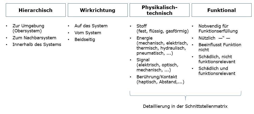
Documentation with MS Office Tools (PowerPoint, Visio etc.) Interfaces are classified into:
Physical-technical (Energy, Material, Signal,...)
Operating direction
Functional
The interface scan be concretised further and components can be assigned with the help of Interface Matrix
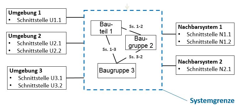
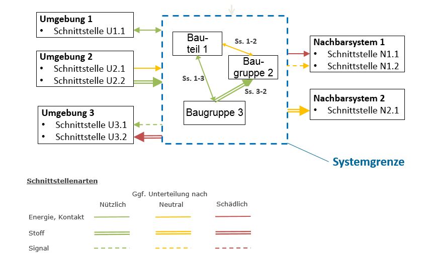
Fig. 1: Boundary Diagram: Classification of interfaces at the system boundaries (Source: Dietz Consultants) Fig. 2: Boundary diagram: Clearly structured representation, FMEA block diagram (source: Dietz Consultants) Fig. 3: Boundary diagram: structure with classification of interfaces, FMEA context diagram (source: Dietz Consultants)
2. Procedure (How?) Determination of the System Boundaries
Functional approach (no consideration of assembly orders, BOM structures etc.)
Determination of the external interfaces to the environment and to the adjacent systems
Use of checklists, requirements specification, legal regulations etc.
Also includes visual interfaces (e.g. labelling): Signal
Inclusion of the different operating conditions in the whole life cycle, misuse is also an operating condition
Differentiation according to material, energy and signal
Touch/Contact is a special case of the energy interface
If required, functional assessment: useful/harmful/neutral
If required, separate structures for the operating conditions, e.g. assembly, operation, service
Description of the functions on the interfaces
Are accepted in the FMEA, ordirectly described in the FMEA,
if required creation of the internal system structure
The same manner as in FMEA:
Functional structuring instead of BOM-based structuring .
Determination of the internal interfaces
Like external interfaces (point 2 and 3)
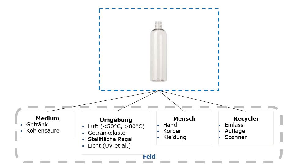
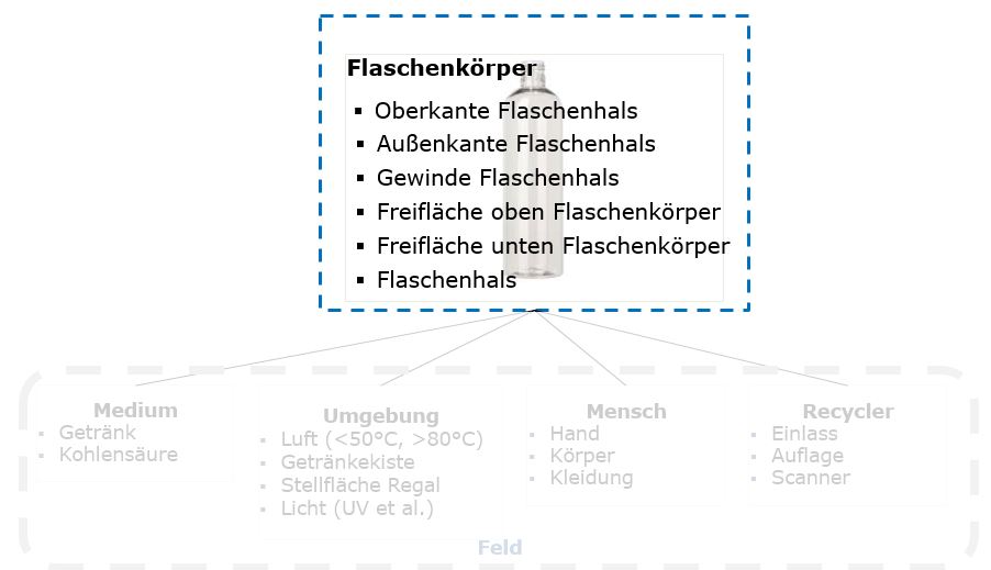
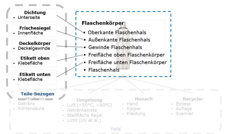
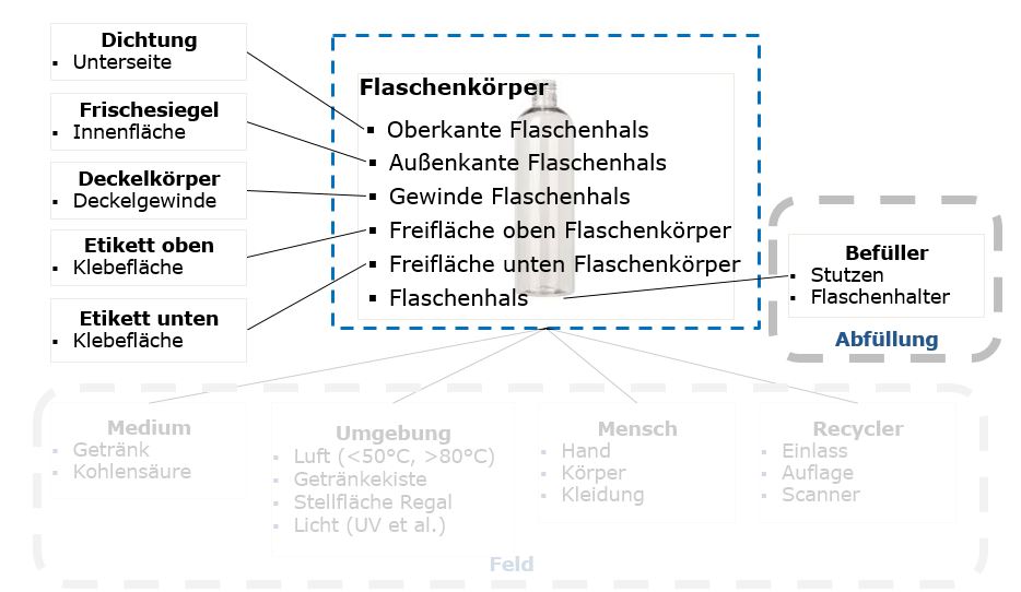
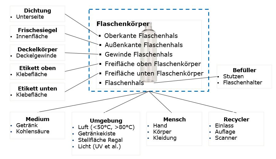
Example - Bottle Fig. 4: Example bottle - interfaces in the field & operating conditions, FMEA block diagram (Source: Dietz Consultants) Fig. 5: Example bottle - interfaces subsystem bottle body, Boundary Diagram FMEA (Source: Dietz Consultants) Fig. 6: Example bottle - Internal interfaces, FMEA block diagram (Source: Dietz Consultants) Fig. 7: Example bottle - Interfaces in the "Filling" operating state, FMEA Boundary Diagram (Source: Dietz Consultants) Fig. 8: Example Bottle - All Interfaces, FMEA Block Diagram (Source: Dietz Consultants)
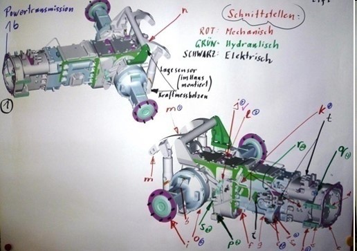
Example - Drive train Fig. 9: Example - Identification of the interfaces of a powertrain, FMEA Boundary Diagram (Source: Dietz Consultants).
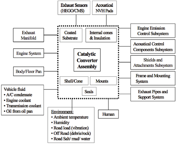
Example - Catalyst (Ford) Fig. 10: Example - Boundary Diagram for a Catalytic Converter (Ford), FMEA Block Diagram (Source: Dietz Consultants)
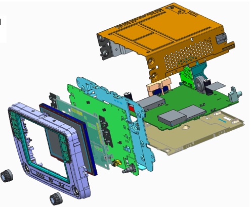
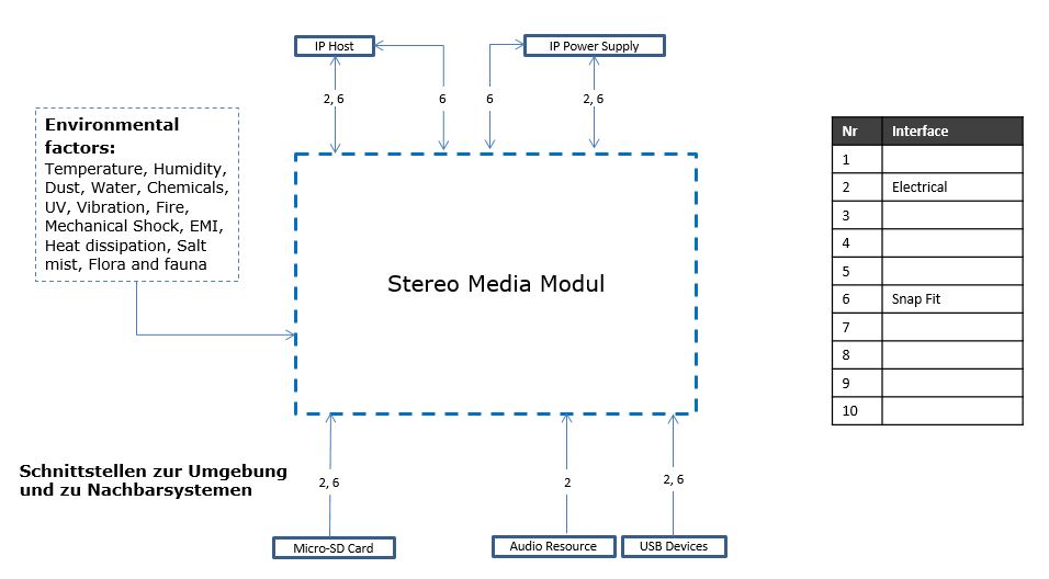
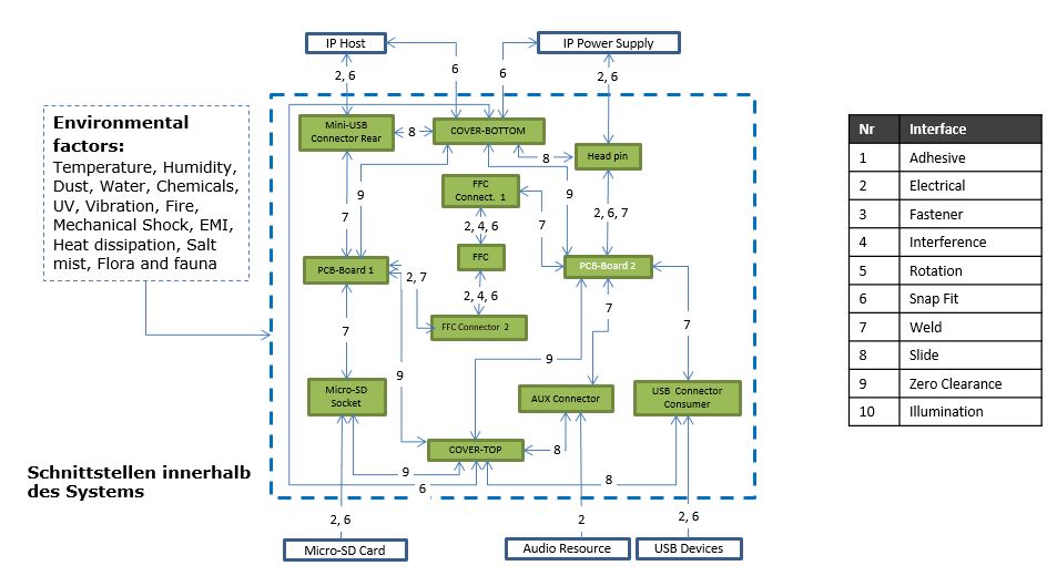
Example - Media module for passenger car Fig. 11: Example - Determination of interfaces of a media module for passenger cars, FMEA Boundary Diagram (source: Dietz Consultants) Fig. 12: Example - Boundary diagram of a media module for passenger cars, FMEA block diagram (source: Dietz Consultants) Fig. 13: Example - Boundary Diagram of the Media Module for Passenger Cars, FMEA Block Diagram (Source: Dietz Consultants)
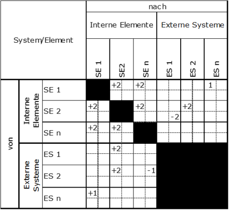
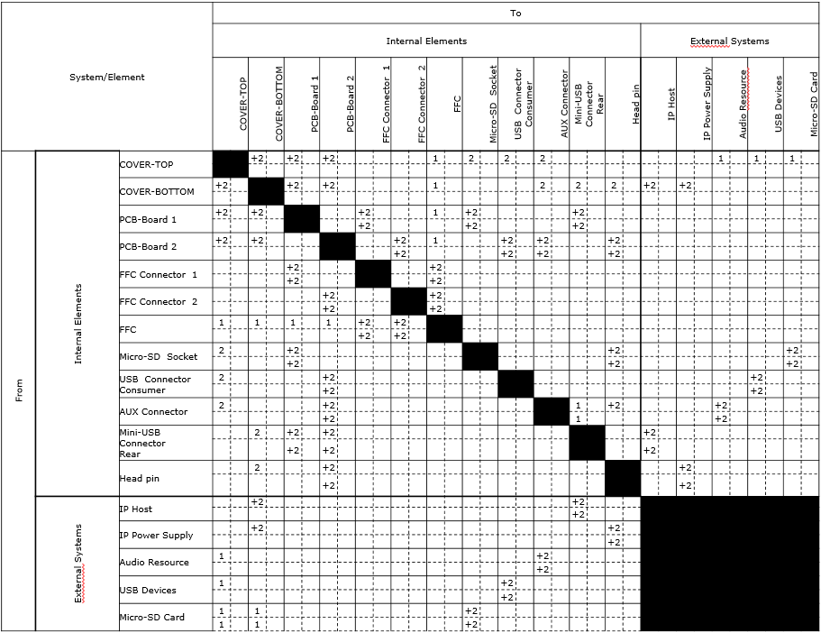
Example - Interface matrix of the media module for passenger cars. Fig. 15: Example - Interface Matrix of the Media Module for Passenger Cars, Boundary Diagram (Source: Dietz Consultants)
We use cookies to enable the functionality of the website. If you refuse cookies, certain functionalities of the website will not be available.