FMEA for SW Circumferences
1. Purpose (Why?)
Functional Networks and Signal Paths
The modeling of functional networks within the development of FMEA is crucial for:
- Achievement of a comprehensive system understanding
- Systematically identification of causes of failure, types and contexts in the course of the FMEA analysis work
Prerequisites for the goal-oriented modeling of functional networks are:
- Know and understand the market requirements ("the voice of the customer")
- Development of verifiable specifications for the design process (eg by means of a data sheet and specification booklet)
As far as software scope is the subject of FMEA, it is likely that the experts will take a path that leads to the basis of the FMEA function analysis for many useful signal paths.
The modeling of signal paths in the form of functional networks can not lead to uncertainties, inconsistencies, and in the sense of the FMEA in FMEA developments.
Justification:
The mapping of the signal path as a function network visualizes only one error of the entire signal path.
The aim of the FMEA is to find the fault and the associated causes at the place of origin and to avoid them efficiently and effectively. Exactly this provides a functional network for a SW circumference based on the signal path NOT! The example of a series connection of n radiators (HK) demonstrates this thesis comprehensibly:
If the first radiator does not function because the flow of the heating medium is disabled, the second radiator can not perform its function of "passing heat through convection and radiation to the environment", even though it:
- Has no cause contributed to this malfunction, and
- Has no failure / is fully functional.
Avoidance and detection measures (eg other design for radiators) would be expensive and unnecessary
2. Procedure (How?)
We therefore suggest the following recommendations:If signal-path-based functional networks are required for system understanding or other tasks, you model them according to the representations known from the FMEA. The work results can be a value in itself.
Do not develop an FMEAfrom this type of network with the negation of the functions, errors, etc.
Justification:
- For the system function "dispense heat by convection and radiation to the environment", the functions of the HK1 to HK n are required in a series connection
- Understand functions as "AND-links" in this context
- The functions of HK1 and HK2 and HKn are therefore required to fulfill the whole function
- Understand, in this context, the types of faults as "OR connections": The error "does not emit heat or heat that is too low due to convection and radiation to the environment" is caused by errors of the HK1 or the HK2 or the HKn.
Here you can see how important it is to discover the origin of the failure, since the malfunction: "... no heat ..." does not come from a fault of the HKn.
Explanatory definition:
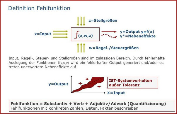
- A "malfunction" of the analysis object exists when the intended function (output) is outside the tolerated target value and the cause lies in the incorrect conversion of the input variables (input) (fig. 1).
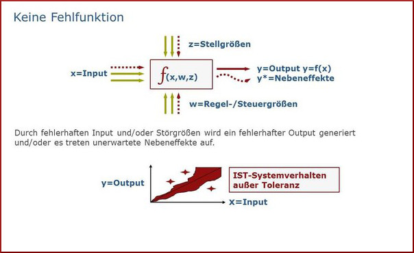
- There is no malfunction of the analysis object if the intended function (output) is outside the tolerated target value and the cause lies in thefaulty inputof the analysis object (fig. 2).
Examples:
Schematic diagram Block diagram:
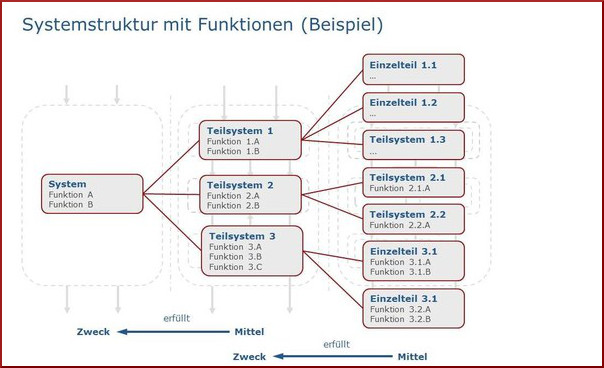
Example:You need to fulfill a specific function in subsystem 2
in 3.1: Function B (Signal to 3.2)
and 3.2: Function A (to 2.2)
and 2.2: Function B (to Output)
Important: Only the output signals are always considered.
The input signal at 2.2 corresponds to the output signal at 3.2. Accordingly, 3.2 is responsible for the correctness of the output signal.
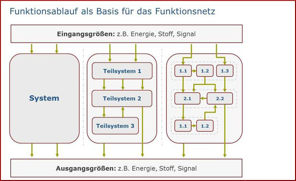
Principle diagram system structure (fig. 3)
System structure with functions (horizontal): Direction of the functional networks in the FMEA
90-degree offset signal paths (vertical): direction of the signal paths (not basically suitable for FMEA)
Principle diagram (fig. 4)
System structure with functions (horizontal): Direction of the functional networks in the FMEA
90-degree offset signal paths (vertical): Direction of the signal paths (not fundamentally suitable for FMEA)
Tips:
- In the case of the failure consideration of a system[/tooltip]element, invariable inputs are always from i.O. fallen out. The FMEA wants to discover the failures at the place of origin, ie the failures that are caused in the system[/tooltip]element itself.
- If, in practice, the correctness of the input signal can not be guaranteed, the receiving system[/tooltip]element receives the additional function: "Plausibilize the input signal". This further functionality has nothing to do with the signal progression, but must also be examined again for possible errors. For this purpose, however, the receiving system[/tooltip]element must "know" that the output signal of the sending system[/tooltip]element is uncertain. Here, we would like to point out the importance of matching interfaces in particular if two or more suppliers are involved in the fulfillment of the overall functionality. Often, in the process, the requirements to the customer are fulfilled by each supplier, but which doesnt not check the reciprocal requirements.
- The functional coordination of the interfaces is crucial. Especially if two or more suppliers are involved in the fulfillment of the overall functionality. Although often the requirements of the customer are met by each supplier, the system requirements are not checked.
- The thought model is recommended to assign "responsibility" to the sender. On the one hand, this must guarantee an i.O. signal, or he is obliged to inform the receiver of possible uncertainties
3. Result
In a FMEA that is correctly constructed in the sense of the method and the company objectives (avoiding failures at the origin site at low cost), the functional levels correspond precisely to the system levels. The FMEA is not suitable for displaying and not intended for signal processing. It is up to everyone to decide whether apart from this all he wants to display it in FMEA software. From this, however, to derive an FMEA, we do not consider it appropriate.
- The function levels correspond to the system levels
- Failures can be avoided cost-efficiently at the point of origin
- The FMEA is not missused to model signal paths