Avoiding Analysis Chaos in FMEA with Growing Software Scopes
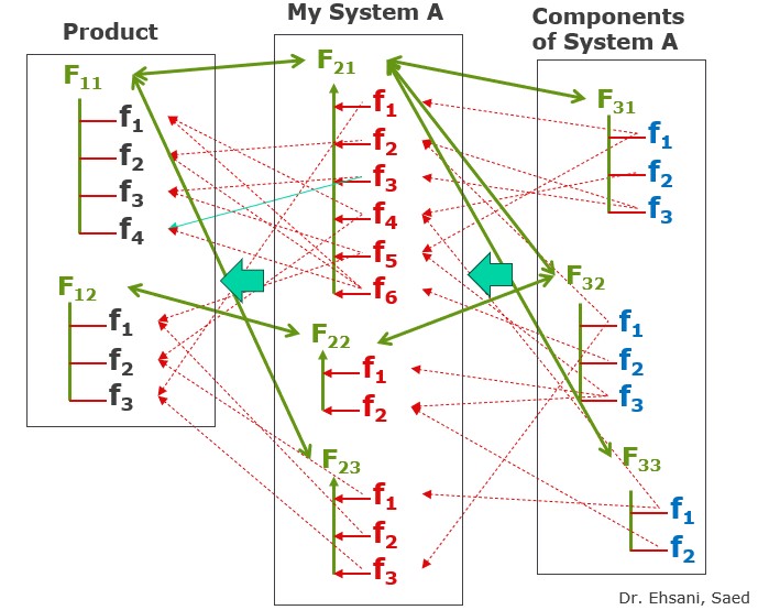
Decompose Customer Features over Functions
1. Challenge / Task (Why?)
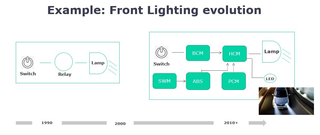
In the modern world, even simple features like “turning on the light” have functionally changed significantly. The evolution of front lighting from 1990 to 2010+ is a perfect example of increasing complexity in mechatronic systems and software-intensive products. In the early 1990s, a vehicle’s front lighting was relatively simple. Only a few components with partial functions were involved. However, over time and with the advancement of technology, this has dramatically changed. Today, a multitude of control units are involved in realizing a comparable feature for the customer. This has increased the complexity of the systems and poses a challenge for modeling in FMEA. Since the models for technical risk assessment must accurately reflect the physical reality in terms of causes, types of failure modes, and consequences, FMEA cannot escape this fact.
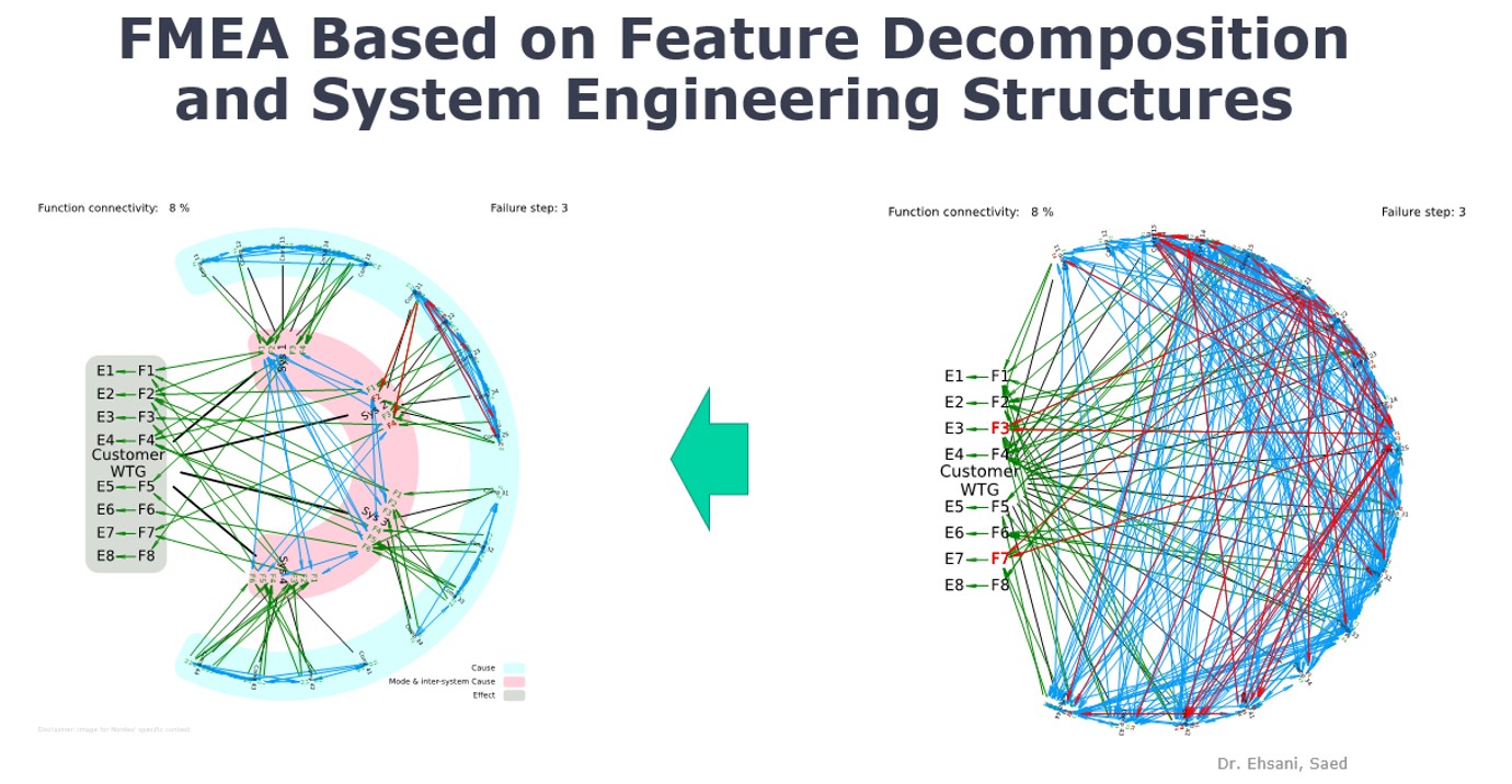
The result is complex function and failure webs, the modeling of which requires a high expenditure of time. This can lead to delays in product development and impair the efficiency of risk assessment.
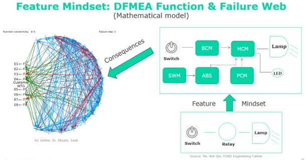
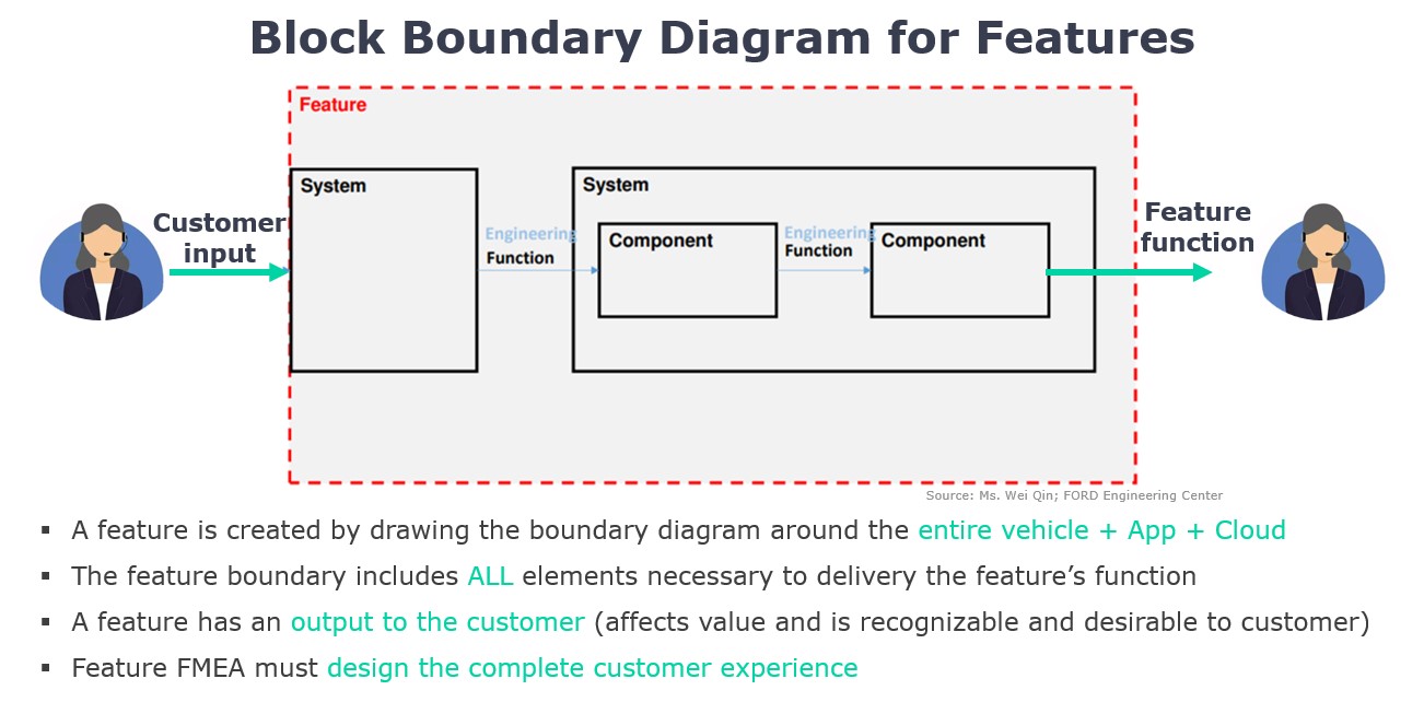
The “Feature Mindset” in FMEA is an approach that aims to reduce the complexity of the function and failure webs. Instead of looking at the entire system as a whole, it is partitioned. This allows for a more detailed and focused analysis.
2. Objective
Present solutions to overcome these challenges and improve the efficiency of risk assessment.
3. Approach (What & How?)
The features are analyzed in separate block diagrams. Each diagram shows the systems and components involved for a specific feature. This step is crucial to gain a clear understanding of the functional requirements and the components involved. After identifying the features and their involved components and based on these relationships, the function, failure mode, and risk analysis is carried out. Methods such as FMEA or simplified procedures like HAZOP are used. In this phase, each feature and each component is analyzed individually to identify potential failure modes, their causes, and possible effects. The risk analysis assesses the risk of each identified failure mode based on its probability of occurrence, the severity of the effects, and the ability to detect the failure mode. This helps in prioritizing the risks and determining appropriate risk mitigation controls.The systematic approach to modeling the features and corresponding functions of the involved systems is a key element of this process.
Overall, this approach offers a comprehensive and systematic way to overcome the challenges associated with modeling and analyzing functions and failure web in FMEA. It enables a more effective risk assessment and contributes to the development of safer and reliable products.
4. Application Example: Development of an Autonomous Vehicle
A team of engineers is working on the development of an autonomous vehicle. The complexity of the system is enormous as it includes a multitude of functions and features, such as automatic braking, lane keeping assist, traffic sign recognition, and much more.
With the traditional approach, FMEA modeling would be a challenge due to the high number of involved components and functions. But with the “Feature Mindset” approach and adapting the models of system engineering, the system is broken down into feature and function-based fragments.
For example, the feature “automatic braking” is analyzed separately. A block diagram is created that shows all involved systems and components, such as sensors, brake control, vehicle dynamics, etc. Based on this diagram, a detailed function, failure mode, and risk analysis is carried out. Potential failure modes, their causes, and possible effects are identified. The risk of each failure mode is assessed and appropriate risk mitigation controls are determined.
This systematic approach allows the team to focus on the most critical risks and take effective risk mitigation controls. The result is a safer and more reliable autonomous vehicle.
5. Result
The result of this systematic approach is significantly simpler models for conducting risk analysis. They are more structured and clearer and allow teams to focus on the most critical risks and take appropriate risk mitigation controls. This leads to a more efficient and effective risk assessment and ultimately to safer and more reliable products.