System-based DFMEA – A Systems Engineering approach to DFMEA
System-based Design FMEA combines the thinking behind systems engineering with classic FMEA, thereby creating a clear, logically structured basis for risk analyses of complex mechatronic products. This approach reduces ffailure propagation paths, increases the robustness of product functions, and enables more efficient development processes. It is a modern way of improving product reliability in a structured and sustainable manner.
In a mechatronics product, the design is based on combined disciplines of mechanical, electrical, chemical and control engineering which creates complexity with hidden failure propagation paths. Design complexity leads to higher risk of failure and demands DFMEA to be part of design methodology.
Systems engineering (SE), aka V-Model, is the most trusted way to manage design complexity and to integrate designs of components, often from different engineering disciplines, to design of product that meets customer requirements. The set of requirements that is linked to DFMEA are product reliability requirements which are drivers of robust design.
Reliability is no longer a prestige of a single brand, it is a must-have quality to survive in all sectors. From legacy products such as automotive, aerospace and household machines to new products such as wind and solar customers definition of a robust-product is now the “product with no unscheduled maintenance.” This change requires change in DFMEA methodology.
Why? Because existing DFMEA methodology has not been adapted to the change in product complexity and customer expectations. Often it is perceived as a complex and time-consuming process, detached from mainstream thinking of engineers which slows the product release to market. As a result, engineering experts and project managers see DFMEA as an obligatory task rather than necessary task. It needs to be changed. The core cause is lack of harmony with commonly practiced DFMEA methodology and robust design methodology even though the shared intend of both methodologies is to reduce the failure probability of product functions.
For 20 years I have seen that DFMEAs are performed partially and in rush, e.g. on critical components and before gate review, and actions are parked in order to release the product on time. That can be changed by modernizing DFMEA methodology to meet the market demand.
Systems Eng. & Risk-Assessment
Let’s start with the common target between Robust design and DFMEA. Robust design and DFMEA are both trying to identify non-tolerable, i.e. high-risk, failures and eliminate them via Preventive & Detective Actions (PA & DA) (See figure 1).
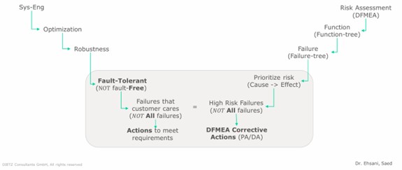
The DFMEA process is usually part of quality control which is in parallel to SE, though they both target quality of the product. We need to close this gap. DFMEA methodology is also focused on product functionality with the objective of improving robustness of the same product functionality. To do so, it first access all the possible risks of fail-ures and second defines a set of PA & DA to mitigate the highest risks.
The SE (V-model) methodology is focused on defining product functionality according to desired customer requirements. To do so, it divides product functions to set of system, Sub-System and Component functions. In this process, design starts at product functions and materialized with components specifications. The design is tested up-ward from components to the product.
The missing link between SE and DFMEA is that:
- these two methodologies are not using the same set of functions & failures. In fact, often DFMEA discussion starts with components possible failure before understanding the component function and its interaction with other components in the same system/product.
- these two methodologies do not follow the same hierarchy of functions & failures from components to product. Often, when DFMEA is performed on physical product with 3D presentation of the assembly, the engineering7manufacturing Bills of Material (e/m-BoM) structure is used for DFMEA.
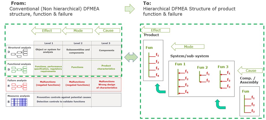
Figure 2 demonstrate these the place to close the gap in these two methodologies.
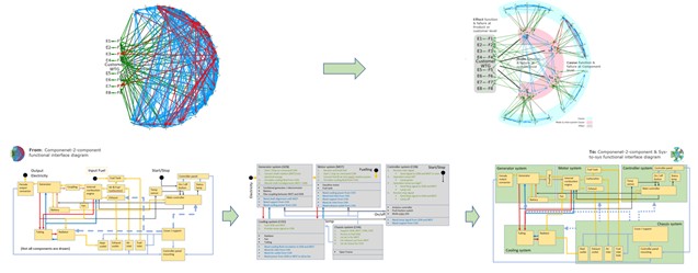
To justify the motive, a mathematical simulation, that compares the probabilistic propagation of failures in both the classical DFMEA versus the system-based DFMEA, has been performed. The simulation promises a considerable reduction on number of possible failure propagation paths in the system-based DFMEA (see figure 3).
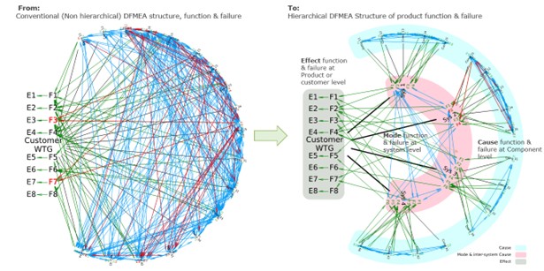
In the system-based DFMEA only the logical interface between functions are considered and the engineering knowledge is used to keep the meaningful possible interfaces between functions.
In other words, if failure is defined to be any possible deviation from intended function, then failure propagation (failure-net) should go through known functional interface (function-net) at the time of design completion. By setting this rule that “failure-net should logically follow function-net”, first connection between DFMEA and SE is established and the system engineering work can be used for DFMEA.
This way, the system-based DFMEA is not adding any extra task to classical DFMEA, instead it combines the systems engineering and DFMEA and brings them to same context. The context is to use the hierarchical structure of product functionality also for DFMEA. This step not only make DFMEA more effective, but also brings it close to logical mindset of engineering for participants.
The proposal here is to enrich DFMEA structure, functions, function-net before moving to failure analysis. After that step, we can:
- take advantage of the existing product hierarchy from SE work to shape DFMEA structure. If the SE work on is not done properly, we can still follow the familiar SE path and define core product design functions and group components based on their main functional contributions and shape the systems in DFMEA structure.
- define system-to-system functional interfaces as only possible failure propagation paths. We can add new paths when there is a logical interface behind to prevent over-populating DFMEA with pure imaginations.
- perform DFMEA on a blue print of product functional hierarchy and logical interfaces but allow constant improvement of structure, function and function-net with increase of maturity
Next we move from theory to practice and show how system-DFMEA can be implemented on a simple mechatronics machine.
Example
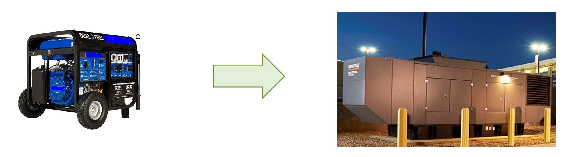
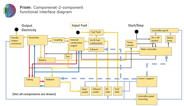
To move from theory to practice, let us implement the system-DFMEA on a simple mechatronics machine: An emergency Backup Power Generator (BPG), see figure 4.
In classical approach, the interface diagram that connects components is what used to start DFMEA (see figure 5). Component are representing functions and failures are associated to them as “failure cause.”
Advantages of the classical methodology is that moderators do not need to handle full product complexity at the beginning. They can start capturing failures of components with help from engineers of same discipline, and the documented DFMEA, shows a fast progress.
But the inherited complexity of the product, if exists, will be postponed or by-passed to avoid complexity of DFMEA document. DFMEA will be done and product quality and robustness is only slightly improved.
Now let us see how the proposed System-based DFMEA can change the approach and outcome. Is there any extra work and is it justified? Or what is the benefit over effort ratio? Let us remind ourselves that the methodology is proposed for multi-discipline mechatronic products and it is assumed that the basic knowledge of systems engineering exists.
Here are prerequisites:
- product requirements’ document exists
- requirement management is performed
- product, system and component functions are defined and structured (or at least the knowledge to shape it in context of DFMEA is available)
- component specifications are documented (from which constraints for components functions can be derived)
- verification and validation document exist
- DFMEA moderation is performed with cross discipline engineering teams.
The backbone of System-DFMEA is the product systematics, which either exists or mist be shaped by grouping components and defining interfaces. The result of this SE exercise for a BPG is shown in figure 6.
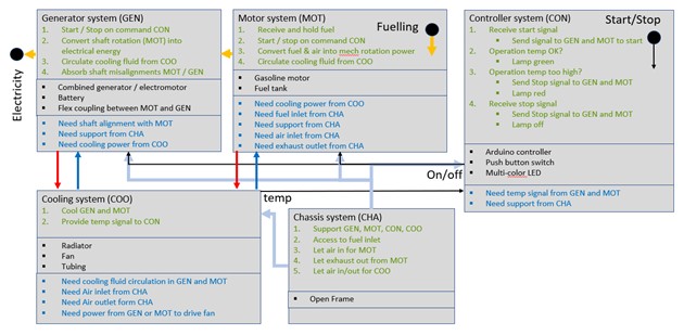
NOTE:Here we see green and blue functions. Green functions (above components) are inherited functions of group of components (first evident) in each system and blue functions (below components) are interface functions requested by other system.
From DFMEA perspective, there is no difference between green and blue functions, and both set are subject to failure. . In DFMEA structure, we enter them at system level and treat them similarly. But they are different in SE interface management so it is helpful to give them different IDs to know where is the origin of each set of functions.
Another benefit of separating Blue & Green functions, from DFMEA is to guide system teams to think about possible set of failures that each system can cause to another systems.
For instance, system A might be robust to a component failure within system A but when system A become aware of effect on other systems, system A design change secures the robustness of neighboring systems. This exercise on its own opens the door to systematically include interface failures in DFMEA.
Back to the BPG example, we can now implement the systematics to the interface diagram and make a two-dimensional interface diagram, where we added system-to-system interface. Now, the DFMEA will be performed in the language of Systems Engineering and the inherited complexity can be added in a controlled manner without chaos, see figure 7.
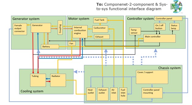
Practically, by managing interfaces, we have identified meaningful propagation paths and created a hierarchical structure to manage complexity before starting DFMEA, see figure 8. The new interface diagram and the systematics excel file are now used to capture and place component failures in the functional structure.
Horizontal & vertical propagation paths:
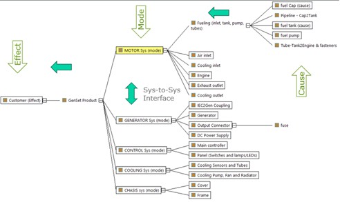
To complete the journey of System-based DFMEA, IQ-FMEA tool from APIS is used to make the functional structure of the BPG, see figure 9.
In this tool, cause -> mode -> effect is from right to left. Cause-functions & failures of components, at right, are linked to the mode-functions of each system they belong to, and similarly, systems functions & failures are linked to the functions & failures of BPG at left.
These 3 levels are corresponding to the horizontal propagation path of failures from Cause to Mode and mode to Effect. As we discussed before, there is also a vertical propagation path of failures through system-to-system interface.
NOTE:
In the horizontal propagation path, the system-level is usually corresponding to mode-level in DFMEA but in the vertical propagation path the mode-function of system A can be the cause-function for neighboring systems B. That means the failure root-cause of system B can be discussed with system B team at system level and PA or DA can be added at system level without involvement of system A components in failure-net.
The system based DFMEA creates:
- Ability of sharing product functional hierarchy between SE and DFMEA. SE provides functional decomposition from product to system, and from system to component (left side of the v-model) and DFMEA use it as horizontal propagation path from left to right
- Ability of reducing DFMEA complexity via considering both horizontal and vertical failure propagation paths and shaping multi-discipline system teams. Moderators will be able to conduct sessions along the engineering design process, i.e. according to SE, and gain the awareness of engineering expertise that is needed for each session.
- Ability of connecting the first 2 steps of AIAG/VDA, i.e. structural and functional analysis, to the engineering design process and build the DFMEA and SE on same foundation
Author: Dr. Saéd Ehsani